
Understanding the Arduino Uno Pinout: A Beginner-Friendly Guide
If you’re just getting started with Arduino, one of the first things you need to understand is the Arduino Uno pinout. Don’t worry—it’s not as complicated as it looks! In this guide, we’ll break it down for you using a simple diagram (see the image above) so you can easily connect sensors, modules, and other components without feeling lost.
What is Arduino Uno?
The Arduino Uno is one of the most popular microcontroller boards used by beginners and hobbyists. It’s like the brain of your DIY electronics project—it reads inputs, processes information, and sends outputs to other devices.
But to make this possible, you need to know where to connect things—and that’s where the pinout comes in.
Arduino Uno Pinout Explained
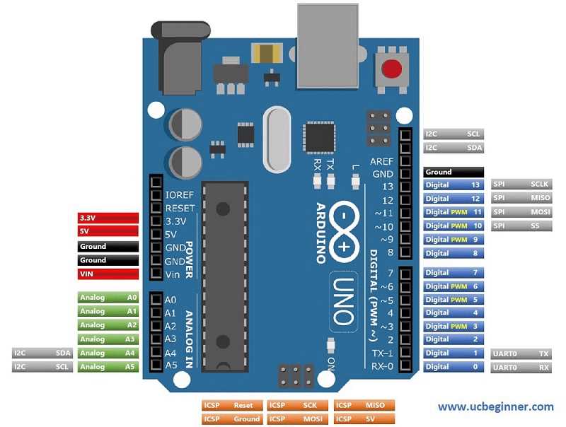
Here’s a quick breakdown of the different sections in the image above:
- Power Pins (Red & Black Section)
3.3V & 5V: These provide power to sensors or modules. Some devices need 3.3V, while others need 5V.
GND: Stands for Ground. Every circuit needs a ground connection.
Vin: If you want to power your Arduino with an external power supply (like a 9V battery), this is where it goes.
- Analog Pins (Green Section)
A0 to A5: These pins read analog signals from sensors like temperature or light sensors.
For example, if you connect a light sensor to A0, it can send varying voltage levels based on light intensity to the Arduino.
- Digital Pins (Blue Section)
D0 to D13: These are used for digital input/output.
Pins marked with “~” (like D3, D5, D6) also support PWM (Pulse Width Modulation), which helps you control things like motor speed or LED brightness.
- I2C and SPI Pins (Grey & Orange Sections)
I2C (SDA, SCL): For communication with sensors and displays using only two wires.
SPI (MOSI, MISO, SCK): Another communication protocol for fast data transfer with devices like SD cards.
- UART Pins (TX, RX)
Used for serial communication with your computer or other devices.
Why Understanding Pinout Matters
Knowing the pinout will save you a lot of trial and error. It makes connecting your components much easier and ensures you don’t accidentally fry your Arduino by connecting things incorrectly.
Final Thoughts
Now that you understand the Arduino Uno pinout, you’re one step closer to building your first project. Whether it’s blinking an LED or controlling a robot, the pinout is your roadmap.
If you found this guide helpful, don’t forget to bookmark it—because you’ll come back to this diagram often as you work on your projects!
FAQs on Arduino Uno Pinout
1. What is the Arduino Uno pinout?
The Arduino Uno pinout is a diagram that shows all the pins on the Arduino Uno board and their functions. It helps beginners understand where to connect sensors, modules, and other electronic components.
2. How many pins are there on an Arduino Uno?
The Arduino Uno has a total of 20 input/output pins, which include:
14 digital pins (D0–D13)
6 analog pins (A0–A5)
Along with power pins, I2C, SPI, and UART pins for communication.
3. What is the difference between analog and digital pins?
Analog pins (A0–A5): Used for reading continuous signals, like from temperature or light sensors.
Digital pins (D0–D13): Used for reading ON/OFF signals or controlling devices like LEDs and relays.
4. What is PWM on Arduino pins?
PWM stands for Pulse Width Modulation. Pins with a “~” symbol (like D3, D5, D6) can output signals that look like analog signals, which is useful for controlling motor speed or LED brightness.
5. What is I2C and SPI communication in Arduino?
I2C (SDA, SCL): A two-wire communication method for connecting multiple devices with fewer pins.
SPI (MOSI, MISO, SCK): A faster communication method used for sensors, SD cards, and displays.
6. Can I power Arduino Uno with a battery?
Yes, you can power the Arduino Uno using the Vin pin or the DC barrel jack with a battery or external power supply (7–12V recommended).
7. How do I know which pin to use for my project?
It depends on your component. Check its datasheet or tutorial—it will usually specify whether it needs a digital, analog, or communication pin.
8. Can I use all the pins at the same time?
You can use most of the pins simultaneously, but power limitations and coding logic might restrict how many devices can run efficiently on the board.


This is another great delivery, Mahesh. Thanks so much
Thankyou david